
Wind Turbine Construction Course Glücksburg 2015 – THE REVIEW
The course was such a success! Both participants and educators were very pleased with the results. Since we were all very busy during the week running around to get things done we could not find time to write you our great adventure. Now that things have settled a little and the students went back to Denmark with their turbine, we finally have the time to take a look back to the highlights of the course. It took place at the artefact center for sustainable development in Glücksburg, Germany. Participants were a group of american students, currently on an exchange program in Denmark.
Read about the preparations of the course HERE
We even got an article in a local newspaper about the course! See HERE (In German)
Monday – Day 1 – Introduction and training
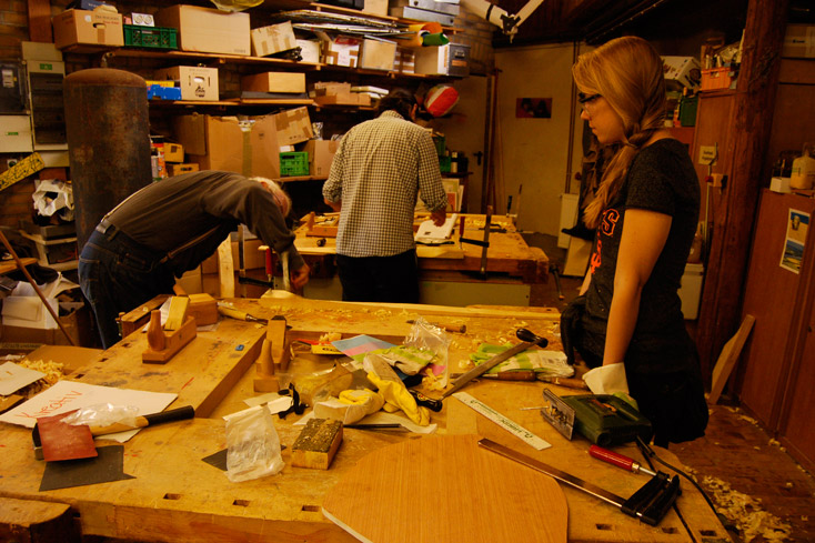
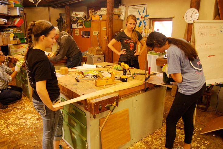
The students arrived at the artefact place late morning, had lunch and we started working straight away. We started with a quick presentation of the crew and our backgrounds. This was followed by a debate on how the participants wanted us to work together during the week.
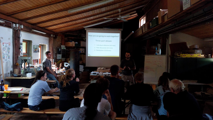 Our three-part debate on how we are going to work together
We agreed the fact that the course is supposed to be fun and the participants empowered through direct work. The safety and timekeeping responsibilities were shared amongst all in a sign of mutual respect and trust. We also decided that the division of tasks was not group oriented so that participants could change from one workstation to another at their own will.
An important concern voiced by the participants was their limited experience with the tools involved in the fabrication process of the wind turbine. Wood carving, welding and wood cutting were, in a way or another, new to everyone. We decided that it would be best to give the participants a general introduction to all of the tools during the rest of the afternoon through some practical exercises. Once we set our goals for the week we continued with a presentation about the “2F Piggott turbine design”, wich has ferrite magnets instead of neodymium and 2 meters in diameter.
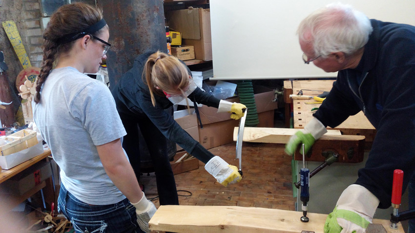 Wood practical exercises
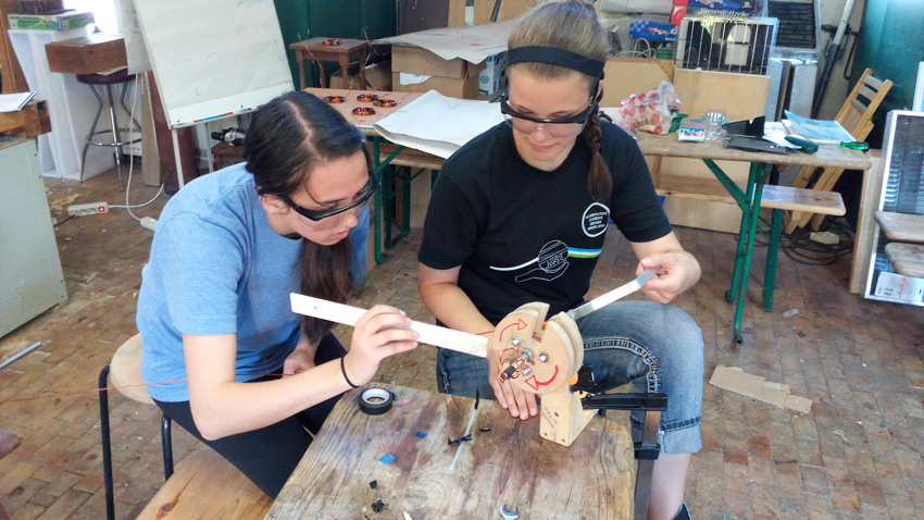 Winding the first coil
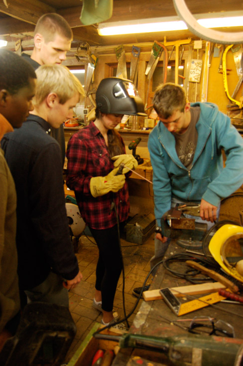
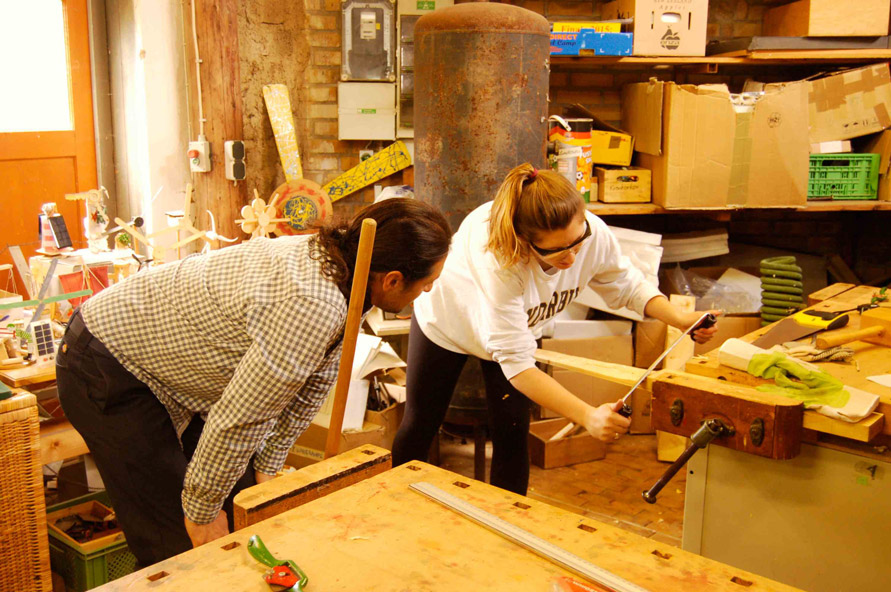
Metal practical exercises
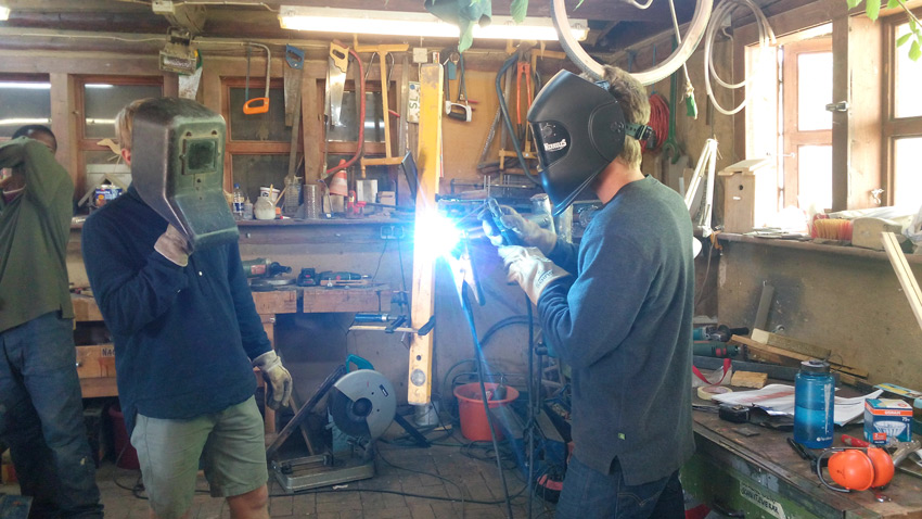
Welding was particularly challenging to the group. Everyone was interested in trying it out and the difficulties (the precision of the welder’s gesture or the reduced visibility during welding) of the task made it very exciting to everyone. By the end of the first afternoon it was quite clear which activity was personally interesting for each participant, and somehow it set the division of tasks for the rest of the course.
Tuesday – Day 2 – Wood, electric and metal working
In the next day the participants spread themselves out across the three different work stations: wood, electric and metal.
Wood workstation
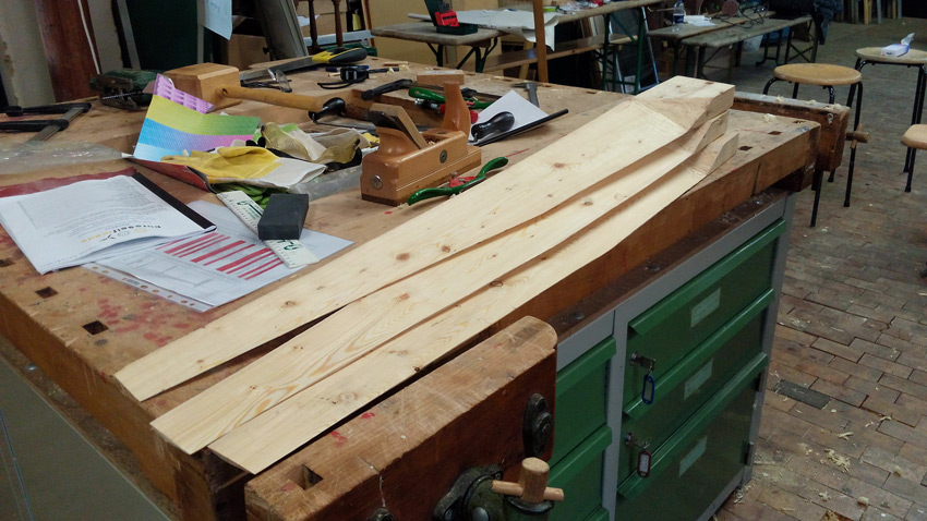
The greatest surprise of the workshop, the wood work station went beyond our expectations. Most participants were involved in it and the blades were carved at neck breaking speed. We used Hugh Piggott’s new blade carving process which involves fewer steps.
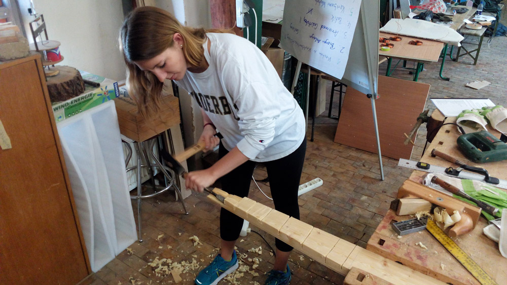
 Blade carving
By the end of the first day the participants managed to finish carving the front of the blades.
Electric workstation
The electric workstation had an advantage over the other stations: the participants managed to finish their first coil in the day before. The first coil was checked and deemed too thick. To compensate that, the central piece of the coil winder was ground down by a few millimeters. All of this was done in day 1.
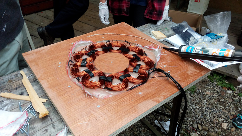
The main work with the participants was to wind the rest of the coils. This long and tedious part of the course is also extremely important due to the role of the coils in the power production process. The participants did not waive and delivered high quality coils as the day progressed.

Winding the coils: how to best test someone’s patience
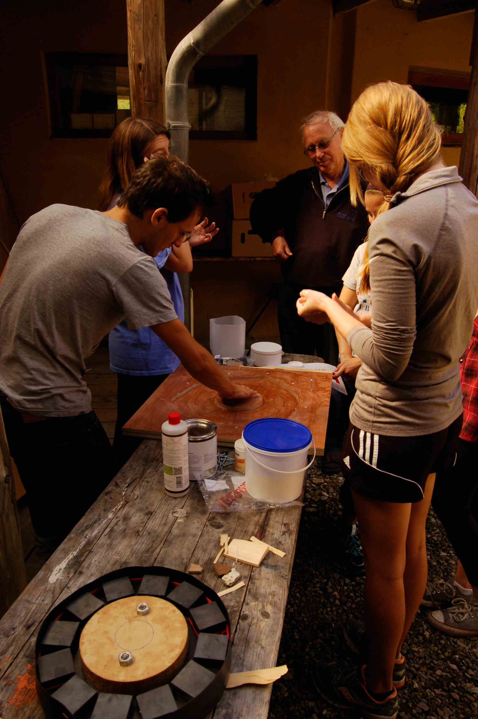
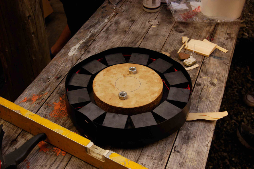
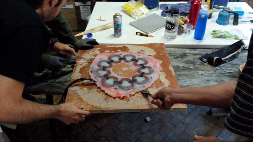
In parallel, other participants placed the magnets on the unfinished rotor disk. As an experience, we’ve decided not to use a jig for placing the magnets and drew their positions straight on the disc. Despite the time gained with avoiding cutting the jig, its absence dramatically slowed down the placing process.
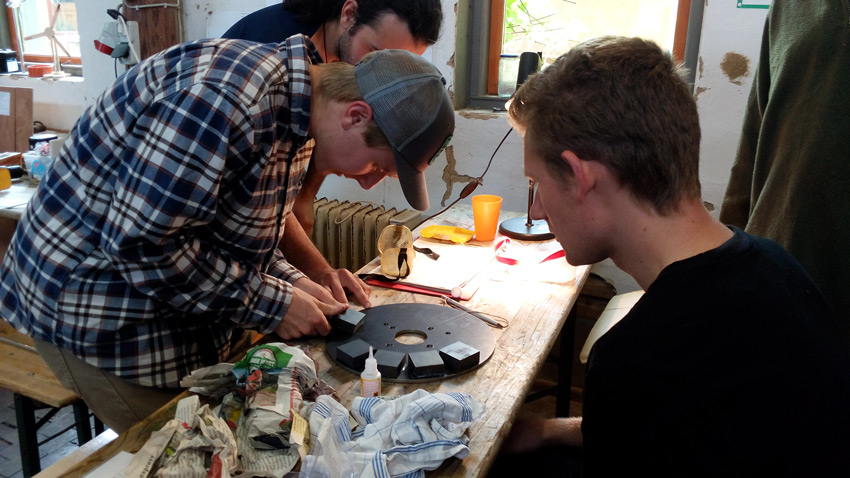
Magnet placing process: delicate and slow
By the end of the day, participants had wound most of the coils and the magnet disk was ready for casting.
 Magnet disk ready
Metal workstation
At the end of day 1 we saw the natural emergence of a “Metal group” from the participants. This group was composed by a few highly-motivated participants who wished to dedicate their time to welding. However, they all felt undertrained and decided to invest most of day 2 in cutting the pieces in the correct shapes.
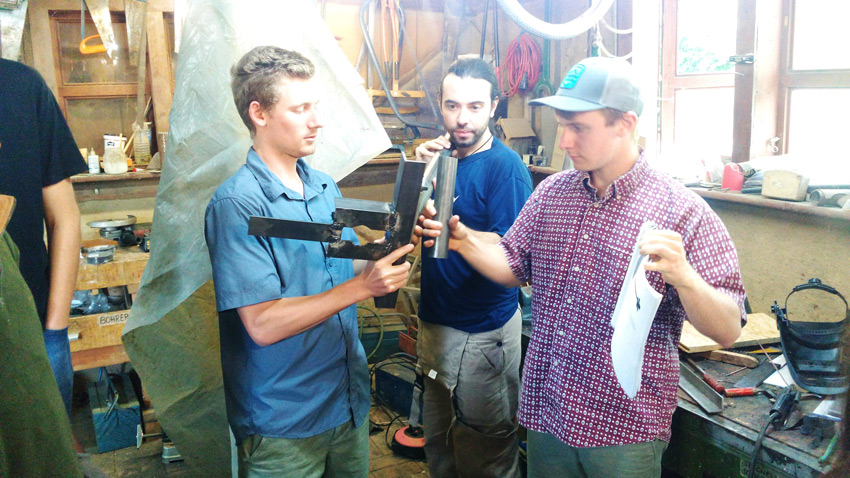 Figuring out how to assemble the frame
Once the pieces were cut, they started with the first welds of the frame. When first progress was made, they could understand even better what the frame should look like in the end.
Summary of Day 2
The progress of the students was phenomenal. Most of the work in the wood workstation was accomplished, leaving it little more than a day of work left. The electrical workstation was well advanced with most of the coils winded and the magnets ready for casting. All the pieces of metal were cut, leaving grinding and welding to be done.
Wednesday – Day 3 – Blades, casting and Frame
With the spirits high we all attacked day 3 with a lot of will to work. Most of the day was dedicated to delicate tasks such as finishing the blades, preparing the molds and welding the frame. The high water mark of the course, casting, also took place.
Finishing the blades
Finishing the blades
Finishing the blades involves carving a curve onto their back side. The underlying difficulty of this task is getting this curve shape right. As the blades are carved, the participants had to constantly check its thickness at different distances from the blade root.
The participants at the wood workstation decided to leave the finishing touches to Jonathan, the result were 3 wonderful blades ready for assembly.

Discussing new progress with other crew member
 The blades after the carving was completed
The assembly of the blades was done after casting. The wood crew worked on fencing two triangles which were used to screw the blades together. This process is delicate since the blades must be as closely aligned as possible. A technique consisting of using 3 measuring tapes was used. The result was the turbine rotor.
 Blade assembly team
Once well screwed together, the rotor was aligned with the metal disk and the four holes of the hub were marked. The holes were drilled by using the two guiding rulers technique. The back triangle was unsrewed so the holes on the front triangle and blades could be slightly enlarged for easing the final assembly.
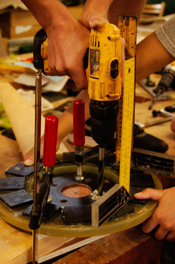 Drilling the holes in the blades with the guiding rulers technique
Once ready, great care was done to properly store the rotor and avoid accidents with it.
Preparation of the magnet disc & stator for casting
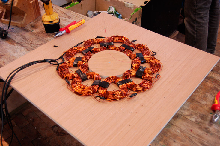
Preparing the rotor and the stator for casting is a very interesting step in fabrication process. The participants have the opportunity of putting together their coils, soldering them in a Y machine and preparing the molds for casting. The final coil was wound in the beginning of the morning, giving plenty of time for soldering them. The 9 coils were soldered in a Y, making the stator of a 3-phase machine.
 Soldering the coils
An island was cut to fit in the center of the stator to leave clearance for the bolts from the rotor to connect both magnet disks.
 Cutting the island
This island piece is used for holding the coils in place for later casting.
 The coils and the island ready for the next step
To test the soldering, the participants used a multimeter for measuring the resistance of each line. The sense of the winding was tested by connecting a battery to a single line and passing a magnet over the windings.
Stator resin casting
With all the windings soldered and secured, it was time to dry run the casting. By dry running the participants put together all the different elements needed during the casting process. The fiberglass cloth used for reinforcing the stator, a bucket for mixing resin, a proper and ventilated space are all things needed during casting.
 Fiberglass cloth cutting
Once the “casting crew” was ready, the molds were greased and all the participants were gathered and casting began.
 Dry run of the casting and greasing the molds
 Coils dropped into the mould
The first part of casting was mixing some resin with very little talc for keeping it mostly liquid. This mixture was poured in the bottom of the stator mold. Then the first fiberglass cloth was put in, followed by the windings. A thicker mixture of resin and talc was prepared and poured on top of the windings. Once the windings were covered in resine the lid was screwed on top of them, closing the stator which was left to dry.
 Stator casting crew
The rotor was prepared through a different process where the mold was replaced by a waterproof belt. The belt was secured onto the metal disk by a layer of silicon during day 2. At casting, the silicon was already dry and the resulting mould ready for casting. The rest of the mixture of resin and talc for the stator was poured into the rotor mold and left to dry. We found it easier to just make a mould that using this belt idea but it was worth a try.
 The magnet disk before casting
After the casting, wood crews worked on the art for the tail. The crew named the turbine S’more Power.
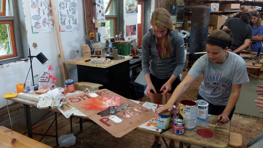 Preparing the tail art – S’more Power is born
Summary of Day 3
By the end of the day most of the work in the wood and electric workstations were finished. The art of the turbine was ready and the welding of the frame was in well underway. The tail metal parts were already all cut and partially welded.
We were happy to finish another great working day and spent one more evening at the bonfire!
Thursday – Day 4 – Unmolding, alternator assembly, frame and tower preparation
This day was dedicated to assemble all the elements of the turbine. The stator and rotor were taken out of their molds, the frame was finished and they were all put together. While work was being finished in the metal workstation, the tower was prepared for hoisting.
Finishing the frame
 The last weldings – tail vane brackets
The metal crew could finish all steelwork right on time and they found even time for another ambitious project: a turbine stand! (see pictures further down) The participants could gain useful experience in welding and steelwork in general. Some of the brought a little experience to the course to start with. In the end we had a professional welding crew!
Unmolding the stator and rotor
Removing the stator from its mold is a delicate task as some parts always end up stuck together. The trick is to take it slow and avoid forcing the stator too much. Both the stator and the rotor came out without any problems.
The rotor and stator were ungreased and put aside for assembly.
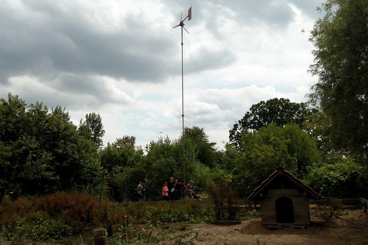
Tower preparations
To hoist up a turbine, the tower must have all of its guywires prepared and well anchored. A winch must be used and a ginpole correcly connected. The electric wires that bring the power down from the turbine to the ground must be correctly installed inside of the tower.
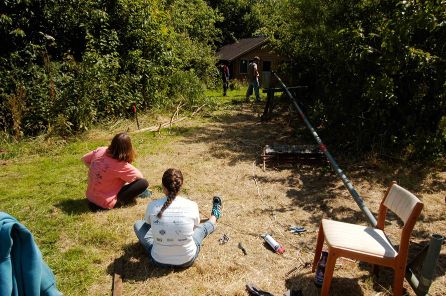 The tower hoisted down and being prepared
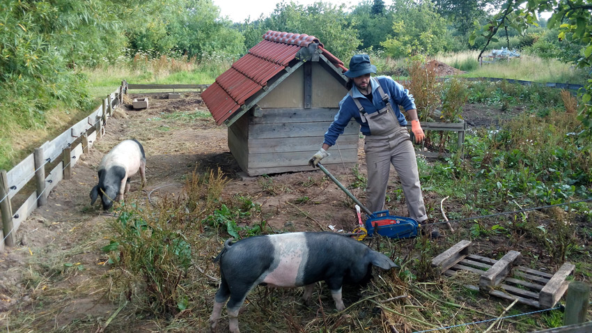
After inspection we found several problems with the tower and its installation that cost us several hours of work. We found the tower without any cables inside, some vegetation covering the way to the guywires, the ginpole bent and the winch anchor point inside of a pig pit!
Despite these challenges, we managed to find a way to pass the cables inside of the tower, we prepared the guywires correcly and removed the vegetation (with a machete!).
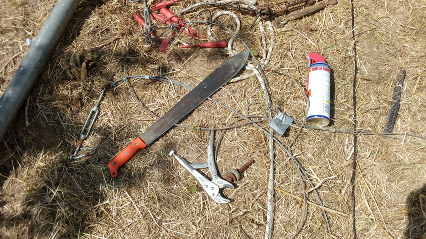 Tools of the trade. Machete-fun-time guaranteed!
Against all odds, we managed to find a winch. We thank the Glücksburg fire brigade for their kind help in borrowing us theirs. We were never alone while winching since the piggy inhabitants were very curious about our mischiefs and always came around to check we were ok.
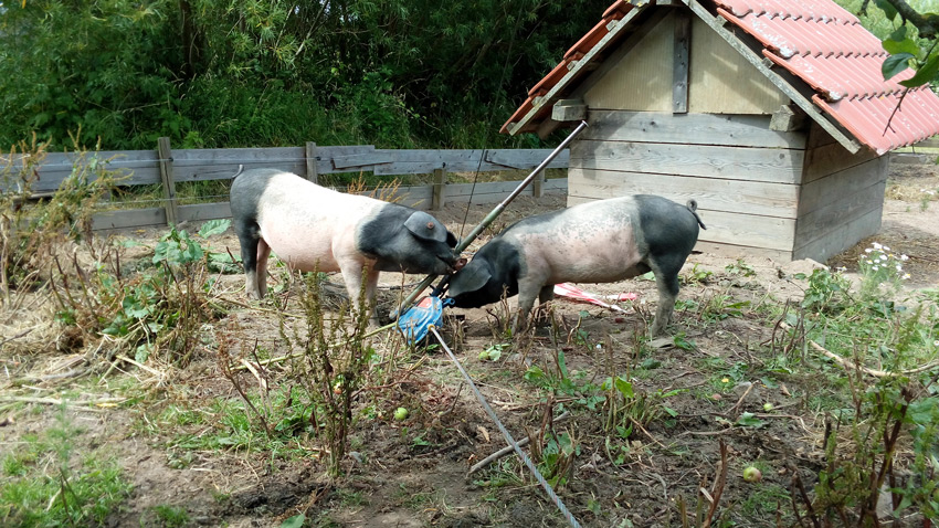
Piggies can go wind power as well!
We did some dry runs during of the hoisting process since it was critical that all the guy wires were tested under no load to verify their capacity. Some of them were poorly tightened and the top guy wire to the gin pole which has the most load during erection slipped out of its poorly tightened connection! Tower was only half a meter above ground, nothing damaged. We checked all the wires after that to avoid accidents during erection.
 Dry run hoist under strict swine supervision
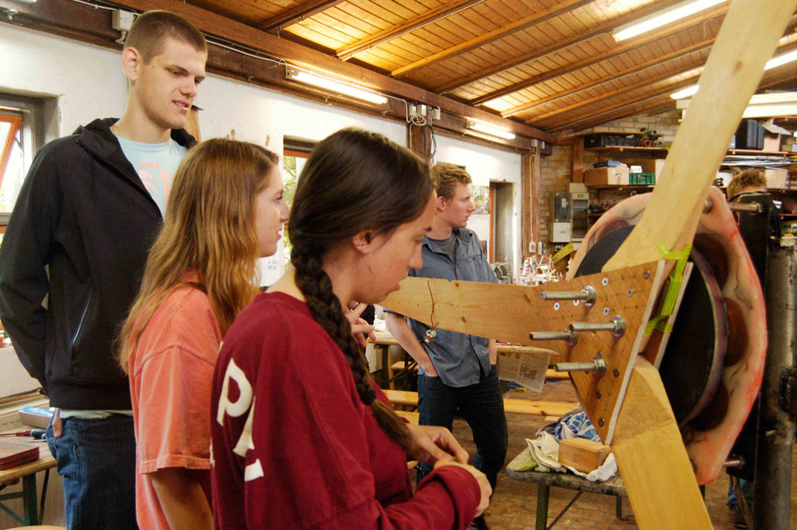
Electric machine assembly and testing
Assembling the electric machine is a straightforward job that requires attention and precision. The stator must be drilled to accommodate the rods that will attach it to the frame while the rotor must be aligned with and attached to the car hub. Drilling the stator is delicate since the hole must be perpendicular to the magnet disk to allow the magnetic flux to flow perfectly through the coils. To achieve this, the hole in the stator must be drilled by using a sophisticated alignment technique. The alignment between the stator and the frame must be done at this moment for it will be permanent once the holes are drilled.
 Jonathan explaining the assembly process
With the holes drilled, it was time to grease the hub. Both of its rolling parts were greased along with its inner tube. They were assembled and the hub was attached to the first magnet disk through 4 stainless steel threaded rods. Once the first magnet disk is secured, the stator was bolted to the frame through its newly drilled holes. These holes can be used for fine adjusting the position of the stator and align it if necessary.
Stator being assembled
The rods attaching the magnet disks to the have a certain number of nuts whose role is to set the gap between the two magnet disk. Some washers can also be added for fine adjustment. When putting the second magnet disk down, it is important to verify that the magnets from both disks are facing each other on opposing poles.
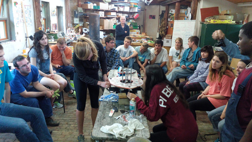
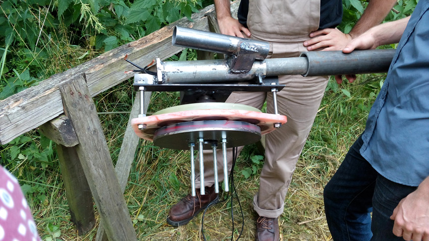
The electric machine was now completed and we could test it. A board with a rectifier was used to connect the output wires and easily access voltages. A digital hand oscilloscope available at Artifact was used to look at the sinewaves and study their form. The output DC voltage was also observed.
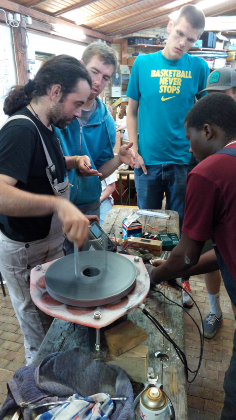 Testing the machine
After the tests, the machine was put on the stand for assembling the rotor. It was done with a little hammering but without major difficulties.
 Turbine head on stand
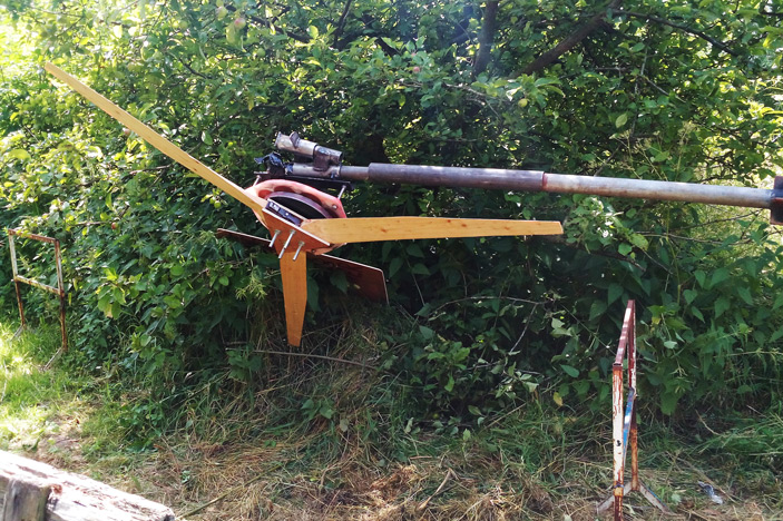
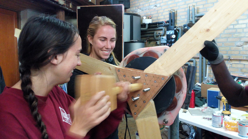 Fixing the blades to the machine: Some delicate feminine touch was needed
Finally, the tail was connected and the turbine was ready for final minor adjustments.
Summary of day 4
By the end of the day, the turbine was ready for balancing and deployment. The participants and crew were exhausted but ready for hoisting up the turbine.
Friday – Day 5 – Hoisting up Smore Power
The final day was quite quick. As the final preparations for hoisting were being done, the rotor was being balanced for the hoist. Tensions were high since no one knew if the tower could take the weight of our turbine and we were in a race against time for finishing before the bus that would take everyone back to Denmark arrives.
Balancing the rotor
Balancing the rotor involves finding the heaviest blade and bring the center of gravity of all the blades close together. The method consists of using several nuts attached to a wire and finding out which distance from the root is the center of gravity. A steel weight is then attached to the root in order to bring this center of gravity closer to the center of the rotor. The participants were directly involved in these tasks.
 Balancing the rotor: Taping weights on the side and finding the center of gravity.
Finally, after adding several pieces of scrap metal to the base of two blades, the turbine was as close to balance as we could make it with the limited time we had.
Hoisting up Smore Power

S’more Power was brought to the tower and connected to its end. We used an adapter consisting of two tubes welded together for connecting the tower and the turbine. The local wind turbine had a wider yaw tube and since Smore Power would be taken back to Denmark with the participants it was important to keep the tower as it was.
 The metal adapter for Smore Power
Once everything was checked and ready, we started the hoist. Smore power went up with no important problems and the tension in the cables could be felt in the air. We almost lost the jinpole in the process but secured it with a rope.
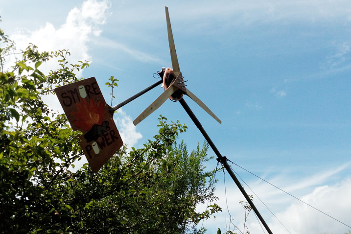 Smore Power going up
 Up and running!
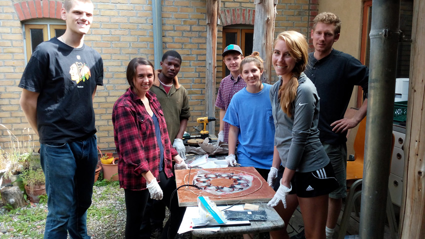
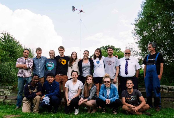
Everyone was excited when our turbine started turning in a light breeze! We did some measurements on the bottom of the tower but we did not have much time. We hoisted it down and brought it to the courtyard near the workstations. But before packing it for the trip, we took our wonderful group picture.
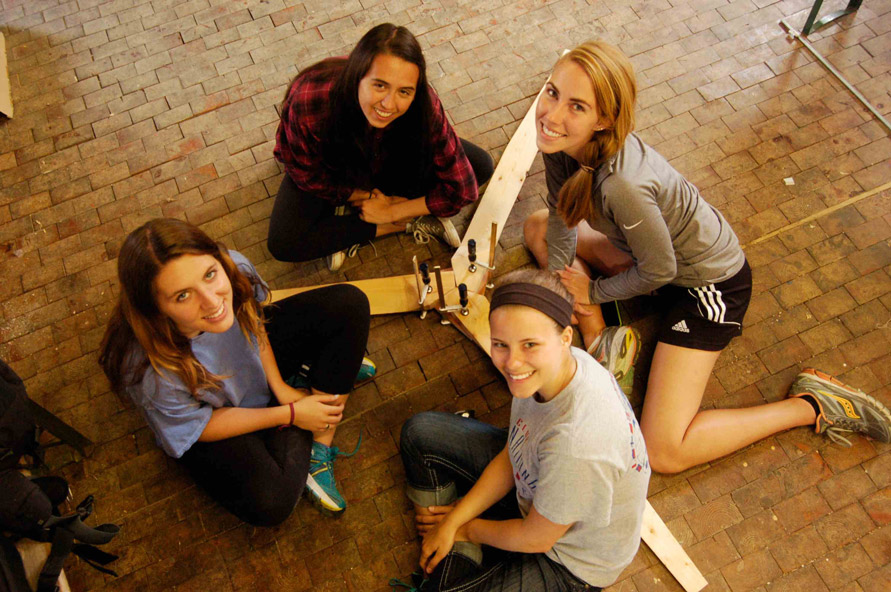
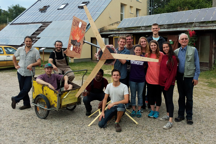 The group and Smore Power posing in success after a great week of work
Final Summary
This course was an amazing experience. Everyone involved gave as much energy as possible to it and the turbine was ready and hoisted on time. We were all exhausted but satisfied with our final result mindful of the fact that everything is possible once we dedicate ourselves to it. We thank the participants and the DIS student exchange program for their great humor and engagement during this wonderful week.
We, the crew, give a big thanks to the site “artefact Glücksburg” for their great involvement in this adventure, with a special thanks to Reimer Backen for running around and making sure we had all the tools and materials we needed. We also say thanks Werner Kiwitt, owner of artefact, for his advice and help during the organization of the course. It would be impossible to hoist the turbine it if was not for the kindness of the Glücksburg fire brigade for lending us their winch. We also thank Jürgen Lassen for his patience while we ran around in his workshop.
Finally, we thank you for reading this post all the way through. Bravo! Please leave us your ideas and remarks. Also, feel free to contact PureSelfMade if this kind of course interests you, your company, your University or your friends.
Article written by Luiz Fernando Lavado Villa and Jonathan Schreiber on PureSelfmade.com

Hi – do you have any designs on building the coil winder?
Hello Bill, you can find the coil winder template in Hugh Piggott’s 2F construction manual!